Introduction
As part of my internship project, I was tasked with making a complete CAD model and then fabricate a sonar-based robot design. The aim of the project was to learn the basics of robotics and working with people teams from different engineering backgrounds. I was given considerable freedom over the design and I took full advantage of it to do what I am best at, making functional yet simple designs.
Tasks
I was provided a list of capabilities that must be present in final project. There are listed below,
- The robot should be able to steer freely in any direction.
- It should incorporate some sort of obstacle avoidance.
- It should have line following capabilities.
- The design should be simple and cheap to fabricate.
- The design should be so that maximum use of inhouse machinery can be used.
- There should be room for adding further capabilities down the line.
Design Process
On my first day, the very first set back were the computing resources made available to me at work and I did not have any personal computer at the time. I was provided with a 2nd gen intel desktop to work with. Realizing that most modern CAD software wont even load at it, I decided to go with an old version of Creo Parametric using my educational licence.
Once I had chosen the software to use, my next task was to design the steering mechanism. At first, I was designing a rack and pinion mechanism similar to that of cars but I quickly realized that this mechanism is going to be too complicated and I won’t be able to source the small gears required to make it work. After spending considerable time staring at the window, a light bulb moment happened and I simply decided to put a metallic ball under the bottom place. Since the sphere can turn in any direction, I won’t have any constraints on the movement. Next, by using the wheels in back, I can steer the robot along a line.
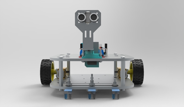
My next task was to design an obstacle avoidance system. After reviewing couple of proposals from my team which ranged from complex machine learning algorithms to radar based solutions, I decided to go with simple, widely available sonar-based system as all other solutions would result in cost over runs. To have a directional control, we loaded the sonar on top of a metal bracket which was connected to servo motor.

Figure 1 Front View of Robot
Line following was relatively simple. We used IR sensors to detect the black line. For integrating the Line following system, obstacle avoidance system, servo and driving and steering mechanisms, we used Arduino sensor board and Arduino uno board. The programming was done by electronics team.
Now that all systems were in place, we needed to know how are we incorporate these systems in a robot body. Since this part of the project was solely my responsibility, I had been very careful in design of other systems so that I can fit everything in a bi-plate design. In these design, two simple metallic plates are joined together with long nuts. I had already given dimensions for holes to screw in place servo, drive motors, uno and sensor boards etc. The bi-plate design allowed me to make a robot of whom guts were easily accessible for educational purposes and leave room for future improvements.

Figure 2 Exploded View of Robot
Results
This was my first working with teams from other engineering field such as electronics and computer science. I learned a great deal of knowledge about working in diverse environment. Additionally, the project taught me a lot about importance of simple and effective design approaches towards complex problems. The project passed with flying grades having ticked all the requirements check marks. Later on, when I got access to better computing resources, I created an exploded view animation which turned out to be my first serious attempt at creating animations. All in all, it will not be wrong to say, this project was a stepping stone in my design journey.


Tools used during this design
Leave a Reply